Step 2: Assembly
Follow the instructions below to solder, wire, and assemble your Linked Lamp. Remember to build two lamps.
PCB Assembly
-
Attach the NFC tag. If you have an NFC tag sticker, stick it to the
bottom of the base (on the inside) before putting in any of the other stuff.
Tip: After flashing the software, you can write your personalized Web App URL to the NFC tag. Then anyone can tap their phone on the bottom of the lamp to instantly open the control app.
-
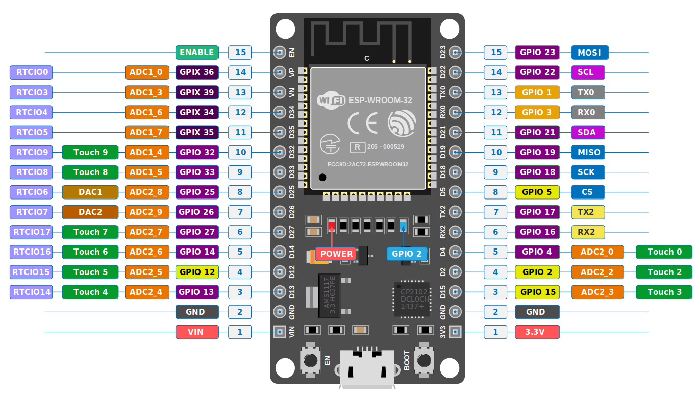
Verify your ESP32 pinout. Before soldering anything, double-check that your
ESP32 dev board's pin layout matches the required diagram.
Important: The ESP32 is soldered onto the back of the PCB (the side without the LED silkscreen labels).
-
Solder all components onto the PCB. Everything is labeled on the PCB silkscreen
— resistors, transistors, and LED positions.
LED orientation note: On 3 of the RGB LED slots, the common anode pin is the 2nd pin from the left. On the other 3 slots, it is the 2nd pin from the right. Check the PCB silkscreen markings carefully.
- Solder the 90° header pins onto the reverse side of the PCB (same side as the ESP32). These will be used to connect the TTP223 touch sensor.
-
Attach the TTP223 touch sensor. Solder it onto the 90° header pins so that:
- The edges of the PCB and touch sensor line up
- The touch-sensitive side faces outwards (away from the PCB)
- It doesn't stick out from under or above the PCB
Tip: After soldering, use wire cutters to cut the excess header pins flush with the TTP223's surface for a clean fit.Important: We strongly recommend flashing the software onto your ESP32 boards (see Step 3: Software) before assembling the lamps. -
Insert the PCB into the 3D-printed base. Ensure the LEDs face upward. Align:
- The ESP32's USB-C port with the dedicated hole in the base
- The TTP223 sensor with its dedicated slot
- The 4 M2.5 screw holes
- Screw in the 4 M2.5 screws. The holes are self-tapping — no nuts needed.
- Attach the diffuser. Place the diffuser over the base and apply a small amount of super glue to hold it in place.